13.10 Correcting any single error: Shor [[9,1,3]]
In Section 13.9 we derived the encoding circuit for the Shor
To start, we encode our qubit with the phase-flip code
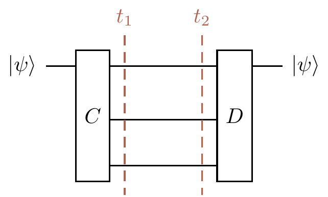
In order to understand how this code works, it is helpful to look at the complete circuit diagram, so let’s build it up in a compositional way.
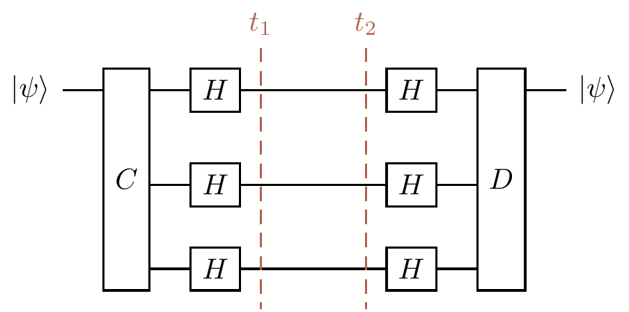
Rather than drawing the entire circuits from Sections 13.7 and 13.8 again, let’s simply draw them as consisting of an encoding gate
and the phase-flip correction looks the same, but with Hadamard gates sandwiching the transmission zone, so
Then we can nest the bit-flip correction circuit into the phase-flip correction circuit by inserting a copy on each of the three wires in the transmission zone, giving us the circuit that implements the encoding of Equation
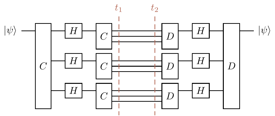
Figure 13.10: Nesting the two correction circuits: one copy of the bit-flip correction circuit on each wire of the phase-flip correction circuit.
We have already seen the idea of sequential composition compared to parallel composition, when we talk about the difference between matrix multiplication
For example, associativity of a composition operation tells us that we can forget about brackets if we just have the same type of composition over and over, since
Looking again at Figure 13.10, we see that we could have composed the bit-flip correction circuits in a different way, placing them one after the other, but we instead wanted to nest them. All that matters in order for us to be able to do either one of these compositions (whether or not we can find any use for it!) is that the number of input and output wires match up. Working with (algebras over) operads has a similar flavour, and you will find yourself drawing lots of little diagrams and then either putting them side-by-side or nesting copies of one inside bits of the other in various different ways. You might find some intriguing pictures if you search for the little cubes operad, or the Swiss cheese operad. One particularly nice introduction is Tai-Danae Bradley’s “What is an Operad?”.
Now, if an
Next, if a
Finally, what about if a
So quantum error correction is indeed possible: we can remove the unwanted effects of decoherence during transmission through a channel. However, this process of encode–transmit–decode doesn’t really cover the practical scenario of computation, since in reality we are constantly trying to process our data, and noise could enter at any moment. One thus has to compute on the encoded states the whole time, whilst also somehow ensuring that even faults occurring during an error correction cycle don’t adversely affect the computation. This is known as fault tolerance, and studying this, using the stabiliser formalisation of Chapter 7, is the goal of Chapter 14.
Although nine qubits is actually more than necessary (we can achieve the same result with a different scheme that only uses five), this code, proposed by Shor in 1995, allows us to more easily see what’s really going on.↩︎
We will explain why this condition of “occurring in different blocks” is necessary in Section 14.7.↩︎
As per usual, any resulting global phase doesn’t matter.↩︎